Even though these designs are un-finished, the fact that the trustees are re-surfacing the MUGA with an ouside surface meant that I had to show them to them to see if they could delay that project until after I'd finished them and sought viability of the plan. One of the trustees is a planning official and kindly took time to discuss it with colleages. The feedback was:
"Yes it was considered today and few points:
It would require both planning permission and listed building consent which is not likely to be considered favourably.
There is scope to extend the Mansion or allow development within its curtilage but this approach would not be acceptable."
I would of course rather have had them review a finished plan that actually had all its features shown to best advantage. This gives us a good idea that we are not doing this for this cycle of surfacing of the MUGA. So we can take our time to make a proper viable plan in the 10-20 year time frame rather than trying to rush something out in the 1-5 year timescale we would have had to work to if we had delayed the MUGA resurfacing works.
A further fly in the ointment is that a private email to a friend who is also an employee of the trustees was sent on to the trustees and miss-understood, where I was describing how costs spiraled in the case of the Bridgend farmhouse bothy (see videos linked on SEDA website below) and how it could apply to my hall plans was re-directed towards the trustees own main mansion plans that have suffered the opposite problem of funders dropping out. Had I been writing with the idea of trustees reading that email I would have been more careful with my wording as whilst if you know of the bothy plans you might link my comments to them, but if you only know of your own plans then I can see how they missaligned my comments. I don't think I'm their favourite person just now!
Just to lay out why their arguments don't fit to their conclusions:
The planning officials arguments are quite week in my opinion, though they have no quarms about stating a very strong 'not be acceptable' conclusion. I expect we can build a roof on the MUGA but we will need to go the community first ground up via the politicians route rather than the much easier nod from the planners route. This makes it a long term plan, not an immediate one.
The first part of the process is to see what you have already, so models are being slowly created of the existing site, you can see occasional updates uploaded to this site.
The designs are importing tree locations, sizes and types from a tree survey, though currently only the monkey puzzle appears as more than just a sized and heighted stick.
If your browser supports it you can view an export of the model in your browser, note the file is >40MB and will take a long time to load so please be patient.
The idea is for the community to build the foundations, then have have the metal frame professionally installed by for example icon-fab in Loanhead, then back to the community to build an OSB3 and timber fabricated I-beam eggbox structure for the walls in units based largely upon the sizes the raw materials are supplied in. We would keep the existing MUGA perimiter fence to discourage raw material theft though given that its quite easy to climb it we should still keep left materials to a minimum. Possibly starting with the frame of the toilet block as a fully timber structure to be a materials store.
We could seed the community of builders by asking the Brigend farmhouse to send an invite out to their list of contacts, as well as our own. They used to have a page about it on their website, though it changed over time so its probably best to look back through the internet archive: Update April 2022, Update Oct 2021, Update Nov 2020, Update Aug 2020, Update Feb 2019, Update Sept 2018, Previous Update.
There is also an interesting writeup on the SEDA website along with videos.
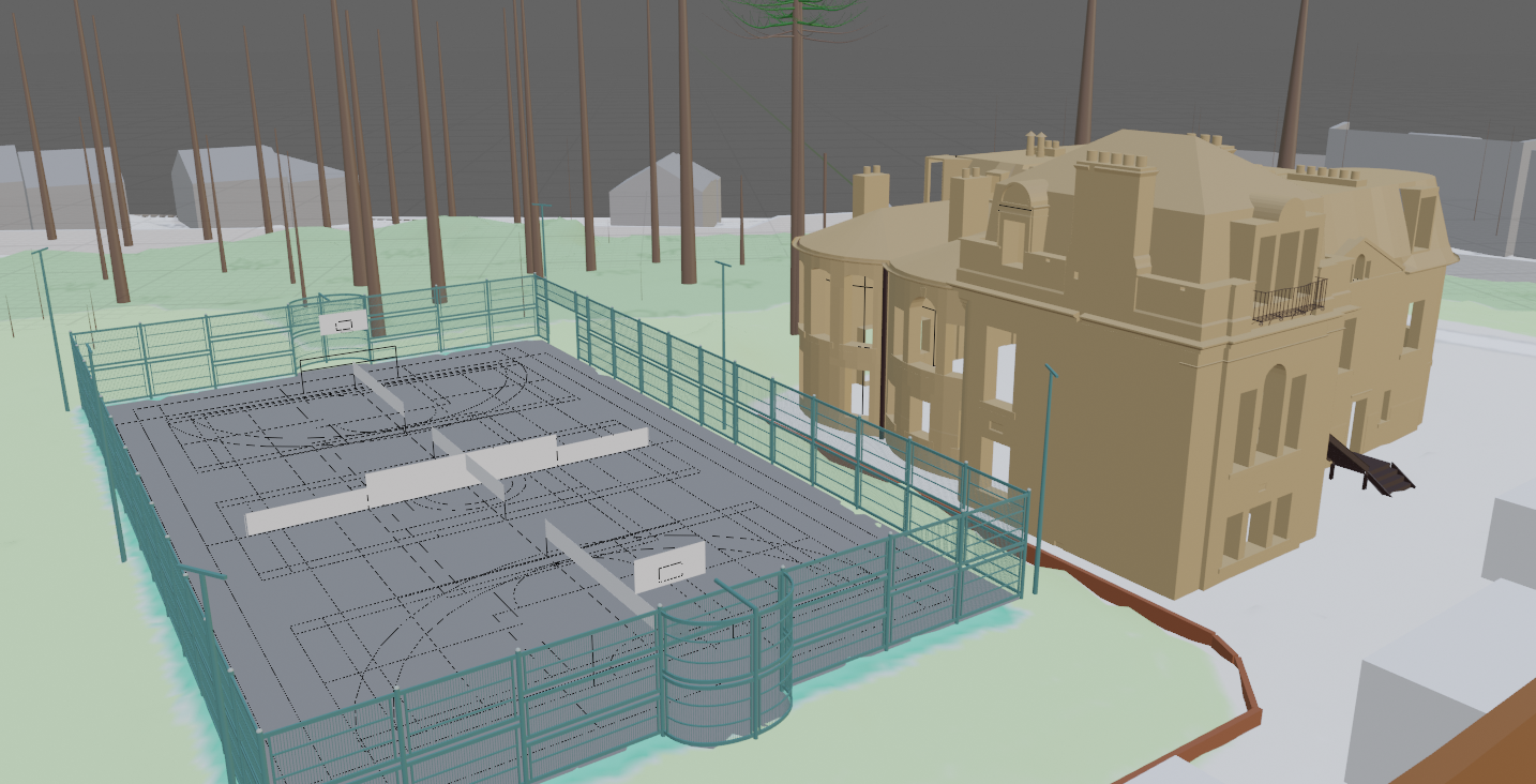
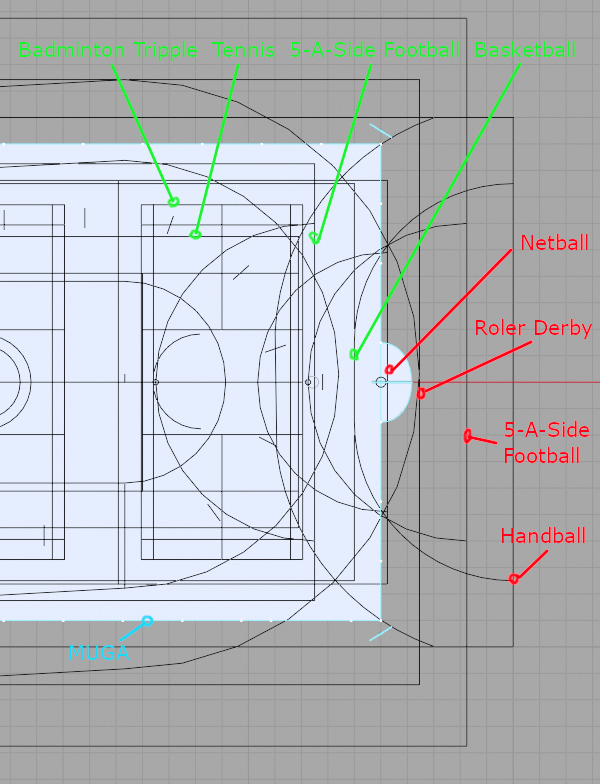
Site as existing showing MUGA with various sports pitches all overlapped to show what will fit:
Sports that fail to fit within existing steel fenced MUGA:
So having the hall built inside the muga will not actually block any additional sport type from fitting. Evidence
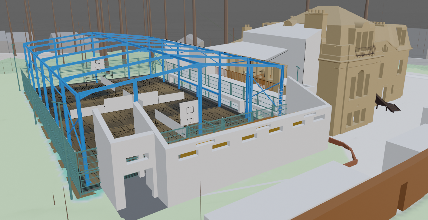
Site from the south showing a steel frame upon which to build the walls and roof.
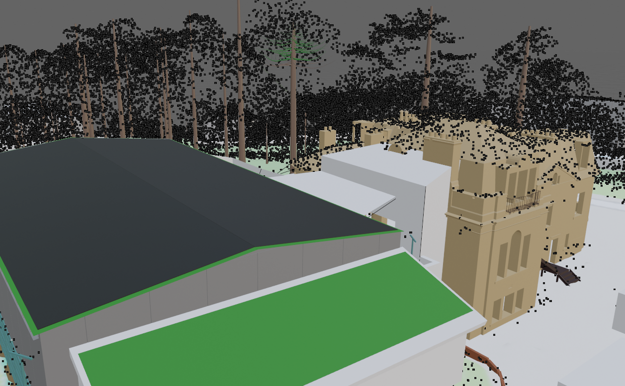
Site from the south showing the green roofed and solar panels also showing LiDAR point clouds being used to verify tree and building heights.
Site from the north showing a possible interconnect level being used as a stage with the side doors of the hall open. Also possible lift placement and 12:1 incline for wheelchair access between stage and hall (actually more visible in the utilities loft view below).
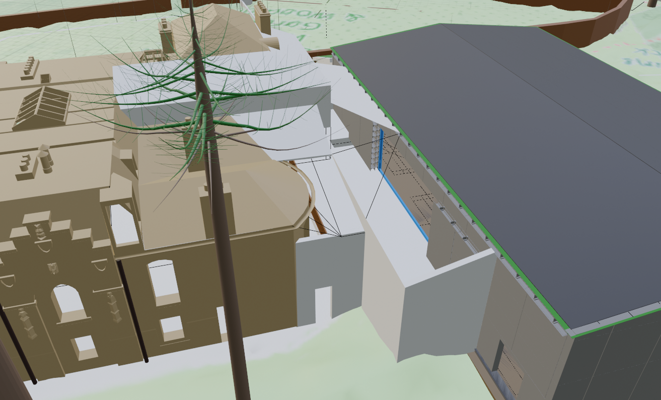
I tried many options for getting a ramp from the lift levels -1.5m and +1.5m to the hall level and unfortunately its just not possible. So wheeled folk need to go outside through the door just next to the lift scurt around the re-leveled land past the new changing rooms and through the main entrance of the hall. It's not actually that much further in terms of wheel rotations than having an internal ramp (18meters long at 12:1), but probably a bit galling for folk to have to go outside. Of course some performances could offer VIP seating at the side of the stage for a few extra special folk.
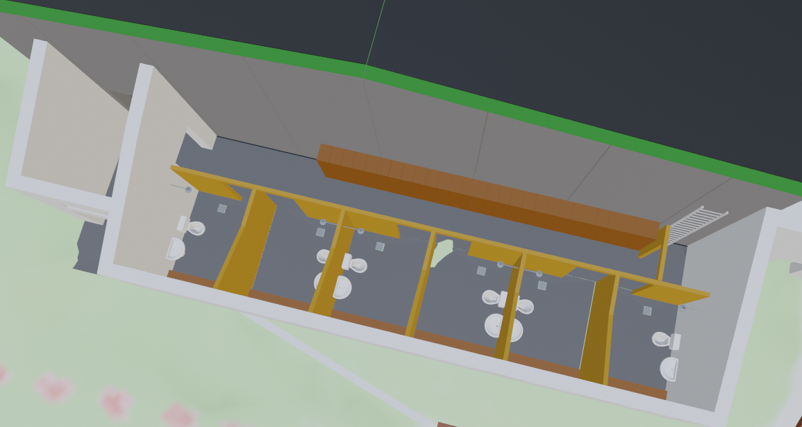
Uni-sex changing rooms with integral bench, shower, toilet and sink. All wheelchair accessable 90cm wide door gaps and the first two have no lockers for extra wide turning circles to allow easy entry.
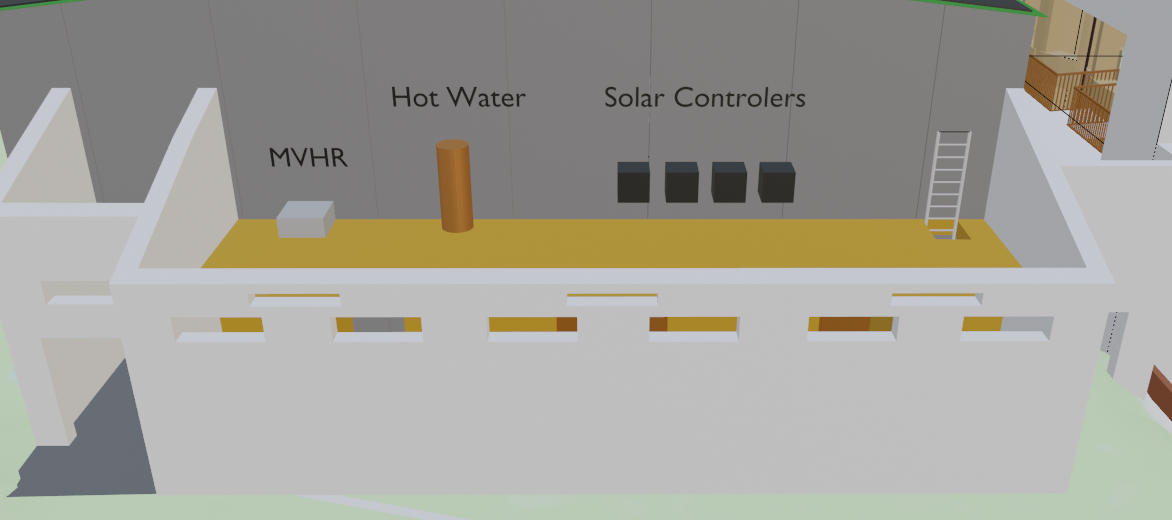
Utilities loft above the changing rooms with ladder access.
The building is to be well insulated with 3x100mm layers of fiberglass loft roll placed within the I-beam structure. The 4.8m long I-beam segments that are bolted to the steel frame provide both significant strength to the structure but also are placed at 400mm(-OSB thickness) intervals giving a much smaller slumpability factor than if the cells were vertically orientated.
TODO: Add calculations.
There are to be no directly south facing windows (prone to over heating) and no sky lights (also prone to overheating and expensive), the south wall has the seedum green roof over the changing rooms, which feature narrow windows tucked under the eves to provide enough daylight for moving about and finding light switches. The main hall's east and west walls will have High up windows under the eves for the same purpose. Given the number of people who upgrade their double glazing I expect we should be able to collect enough recycled window panes during the build process to avoid having to buy any new windows at all. They will be all fixed in place with no opening for both simplicity of construction by the volunteer teem and for security.
The final surface is to be building wrap with taped seams (a breathable but air tight membrane), air gap (to allow evaporation of internal moisture from the building wrap), external render board (An A1 fireproof board), then a thin skim of render mostly over the gaps, then a mural painted over, which would be another community activity possibly involving a slightly different selection of folk.
The guttering and drain pipes will naturally be outside of the building wrap of the structure but to avoid the local youths using them as a climbing frame they will be enclosed. To make the enclosure easier to attach 45 degree angled 45x45x63.6mm triangle battons will be fixed directly over some of the battons that form the air gap as the render boards are fixed, after the pipes are installed the covering boards can then be added before rendering and painting.
I've floated between different ideas for the solar panels and my current thinking is that for this place with the height of the roof and it being surrounded by trees obscuring its visibility from the neighbours there is no visual detriment to having the entire thing covered in panels. The level of insurance required for the historic building next door even not including cover for any of the things that might actually happen is so high (20-30k need to check that) that for The Mansion to be a going concern to avoid financial difficulties in the future as interest waxes and wanes as it it likely to do. A good solid annual income that is not tied to funders whims would be a major boost to the viability of the project.
The current drawing includes 280 panels (1.767x1.041), the plan is to have them as the primary waterproofing barrier. So breathable building wrap, evaperation air gap with battons then panels. TODO: check with suppliers that they can supply panels that have down and to one side flanges to overlap with and be sealable against neighbouring panels allowing for heat based expansion and contraction.
TODO: estimate anual generation and potential income from the panels.
The local population of all ages are used to being able to pop along for a quick kick about or to shoot some hoops during the day. We don't want to block users but by enclosing the MUGA we obviously are going to change the nature of the access available.
My aim is to provide the local community with continued but secure access when the hall is not booked. To facilitate this we need an access control system that lets people re-use existing cards and have them programmed for daytime access. Paid bookings would obviously take prescedence, part of the booking process would be joining the club and picking one of their existing cards to use. For anyone unhappy with us reading the unique number off their card they would be able to buy a fresh card for £2. But its best if we can offer folk no extra charge if they can recycle a card they already have.
I've bought some RFID reading devices and started testing cards, so far some old credit/debit cards are usable, Smile, Nationwide, Oyster (LondonUndergroundOnes) & National Library of Scotland cards are usable. Mobile Phones, Barclaycard Credit cards and UK Passports are not (they use a random UID's with each access). The mobile phones will be solvable by us writing our own app that can make use of the feature.
The process would be that they would give us their details and we'd tap their card on the reader and register them with appropriate access, children would only have hall access when it a reasonable hour of the day. We would need to talk to some parents to work out the specifics. Folk with bookings or club memberships could list all members of their group so whoever is there first would be able to get in etc.
The would then log who is around and when, folk can also tap themselves out as they exit though this is not required as the doors would always let people out. But if any damage is done we would have a good starting point of who to ask about it. We could extend the same control system to the main mansion but perhaps only with paid for secure cards. Or with the addition of a PIN? The general theory being that there won't be much of value to steel from the hall but their might be in the mansion.
I tried to remove the account number from a card but just the small amount of pressure to flatten the numbers was enough to warp the card and render it inoperative. So folk are only going to be happy letting their kids use one of their old cards, we cannot use a donated card from one person with someone else as they would have to trust them with their account numbers even if the card is no longer active in its original purpose and the numbers visually obscured by a 'The Mansion' sicker.
This model and designs have used the following sources:
If you want to do something similar you can use the Scottish Remote Sensing Portal to zoom in on a location and download the LAZ file for your interested location, the gotcha with that site when I tried it is that you need to take the blue outline box with you as you zoom in and turn off the visualise so you can see the map.
You are picking a file representing a 1km square eg NT2768 for The Mansion, this comes from the easting 3[27]*** and northing 6[68]*** values. These are the values from the British National Grid.
This file is too large to import directly to Blender so first I used QGIS to filter it down to just the area of interest, I picked a 180m square around the mansion. The process with QGIS involves adding an Open Street Map layer using EPSG:3857. Then add your downloaded LiDAR point cloud using the British National Grid EPSG:27700. Then using the visual from the map you can zoom into your interested area, the four pointy arrow icon to zoom to your LiDAR data square. Then create a new vector shape file layer, enter edit mode, add a polygon and drop four corner points roughly in the places you want (left click to add a corner, right to finish), you can then use the virtex editor (View-Panels-Virtex Editor) from within the 'Toggle Editing'-'Virtex Editing' right click on your clip rectangle to then be able to manually edit the values to whole meter grid values and square it up etc. Then right click on your LiDAR data Layer and 'Export->Save As...'. Pick LAZ point cloud, and ... to pick a file location, I stuck to EPSG:27700 as the grid is based upon meters, then 'Filter by Polygon Layer' and pick your clip rectangle. I then used import_laz.py to import the terrain as a mesh. Then re-ran the script with ground=false to get another point cloud to use to pick out buildings/trees heights and placements. I then used a screen shot of the OSM layer in QGIS with the clipping rectangle visible to cut down to the square for the texture to apply to the mesh. I failed to get QGIS to export a clipped image from the OSM map layer though in theory it should be possible.
If your target area straddles more than one National Grid square then you'll need to do the above process more than once, they should blend fine as the coordinates will place them adjacent to each other.
For the new design parts of the project I've started to move to auto-generated components where you lay a frame in the 3D space and then run the script to populate it with your elements, I'll upload the scripts I use to github as and when I'm happy with them.